
Meta data switching tools
The purpose of this program is to ease the transition of the meta data used in Sage X3 version 6 (in screen, windows, tables, and objects dictionary) to the new classes and representation dictionary.
Although it will not solve all the transition problems, it can be used as a starting point.
What does this program do?
* It generates classes and representations, and updates data types.
* It is focused on read-only pages support. Generated representations and classes will be limited to read operations.
What does this program not do?
* it will not help to switch the remaining underlying code from a "nested" state to a state where the UI code and the application logic layer are clearly separated.
* it will not solve all the problems associated with the miscellaneous actions linked to the user interface, but it tries to solve some common standard actions such as the management of miscellaneous tables, translatable texts, and so forth.
How does this program work?
It works in two steps:
A detailed log file is produced and displayed by this operation.
Now let's see more in detail how to launch it, what are the expected parameters, what is exactly done, and what are the tricks and limits of use.
This operation can be launched from the Classes menu in the Sage X3 folder. The function code is "AMIGSYR" and can also be launched by using the F7 shortcut and typing the AMIGSYR function code.
The following window is displayed:
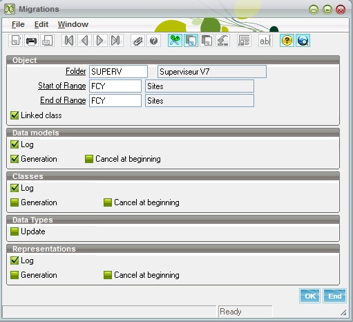
The different options and fields that must be filled are located in several sections.
The first section defines the range of the operation:
The second section defines how the first step is managed:
The third, fourth, and fifth sections define how the second step is managed. Usually, these steps are done together.
In the third section, the parameters are the following:
The fourth section defines only if the data types encountered during analysis have to be updated. This is currently not activated and will be done at a later date. It does not change anything for the class and representation generation.
In the fifth section, the parameters are the following:
It is first recommended:
Once this is done, it is recommended to carefully check the log file, and then to use the data model function (function code is GESAWM) and closely examine the generated data model called SY_xxx, where xxx is the object code.
You can see an example of a data model that has been generated. Only the first tab is filled and thus has to be considered.
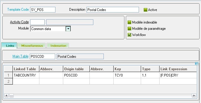
The important points to be checked are the following:
Are all the relevant tables linked to the main table? This is less obvious. The tables that need to be linked are those that might be updated in normal object operations. You can forget all the tables that are used because they are referenced by a data type.
For instance, let's consider the 'SOH' object, linked to the 'SORDER' table. When updating a sales order, the tables that will be updated are at least 'SODER', 'SORDERP', and 'SORDERQ' and probably some others, but not the table 'BPCUSTOMER' (customers), even if the customer will be on the line because a sales order references a customer code. The adopted algorithm uses several clues to find out what are the relevant tables, but sometimes it does not function well. You might have tables that should not be on line and others that are missing. You have to cancel the lines that should not be there and add the missing ones.
Are the links relevant (type of link, key values)? Sometimes, it is quite impossible to get the key values for the link or to find out the right type of link. It is very important to correct this information if you want the second step to work correctly.
If any error occurs, and if the result outlines an error in the object description, you might also correct the object dictionary information and relaunch the operation. In this case, do not forget to select the Cancel at beginning check box.
This step will usually be done after step one execution and manual adjustments. As both steps can be done simultaneously, you have to be very careful if you do not want to get unexpected results. Avoid having the data model generation check box selected if the generation has already been done, or verify closely that the Cancel at beginning check box on the data models is cleared if manual adjustments have been done. Otherwise, you would lose them.
Class generation and representation generation can be done together. There is no need to launch them separately, although this possibility is available if:
The class and representation generation work based on the following, for each object:
The classes and representations have the same name as the table they manage.
Finally, the classes and the representations are validated.
Let's pretend you decide to run the generation for object 'FCY' (site) for the first step only. The log file will provide the following results:
Data model FCY associated with sites (persistent)Main table=FACILITYFACILITY [FCY] +--(0,1)--> COMPANY [CPY3]CPY0=[F:FCY]LEGCPYFACILITY [FCY] +--(0,N)--> BPADDRESS [BPA]BPA0(0)= (not found)BPADDRESS [BPA] +--(0,1)--> BID [BID]BID0=[BPA]BPATYP;[BPA]BPANUM;[BPA]BPAADDBPADDRESS [BPA] +--(0,N)--> CONTACT [CNT]CNT0(2)=[BPA]BPATYP;[BPA]BPANUMCONTACTCRM [AIN] +--(0,N)--> CONTACT2 [CT2]CNT0(2)=[AIN]CNTTYP;[AIN]CNTNUM FACILITY [FCY] +--(0,1)--> COMPANY [CPY3]CPY(0)=[FCY]LEGCPYFACILITY [CPY] +--(0,N)--> BPADDRESS [BPA]BPA0(0)=3;[FCY]FCYBPADDRESS [BPA] +--(0,1)--> BID [BID]BID2=[BPA]BPATYP;[BPA]BPANUM;[BPA]BPAADDCONTACT [CNT] +--(0,N)--> CONTACT [CNT]CNT0(2)=3;[FCY]FCYNow, launch the process again on the same object (FCY), with all the check boxes for selected classes and representations, exactly as shown on the screen:

The result of the generation is the following:
The linked tables created by the generator are found by analyzing the following:
- The environment setup of the Object (tables to open, considered only if they have a link expression, and tables defined in the import section).
- The screens associated with the main window defined for the object. The tables defined in the Reference table block on the screen definition, the first tab, are also retained.
- The link expressions are computed by analyzing the fields and checking if some fields have a type associated with an object that references the table to link on. If a link cannot be found, the "(not found)" text is present in the log file.
Some index might have to be added if there is no easy link. For example, between functions profiles and access codes, a new index on 'ACCES' table is necessary. It is also necessary to create an index if the variable field of a (0,N) link is not in the last position. For example, to have a link for company between 'BPADDRESS' and 'BID', an additional index 'BID2' referencing 'BIDNUM' in the last position has to be created.
Classes are generated by analyzing the associated data models 'SY_*', the object characteristics, the main window, and the screens in this window.
The main class is always persistent. The child classes are deducted by analyzing the tables in the data model (it can be a direct link or a cascading one). These classes are persistent if an associated object is found.
Groups are created every time fields with a dimension are found. When the fields are adjacent in the dictionary and have the same dimension, a given one or deducted from an activity code value, they will be in the same group. The maximum size of a group can either be given or not defined if a group refers to a child class.
When a property exists to count the number of lines of a group in a table, a property is created and associated with the group in the column Property that is present on the Groups block (first screen of classes dictionary).
A file called [class name]_CSTD is associated with the class.
Methods and Operation tabs are not filled; they are not used for read-only pages support.
Only the standard 'Read' method is set. The other CRUD methods will have to be set up manually if needed.
The properties are created with their attributes. They correspond to the fields of the main table and to the identification of the child classes (linked tables). The associated key and parameters are set according to the data type. Sometimes, the parameter value cannot be retrieved automatically and hence will have to be filled manually.
The mapping tab is filled according to the information found in the data model, but the type of link has to be controlled.
The default Creation/Update/Deletion option on the main table are not activated by default. These options have to be linked to the CRUD operation. When they are checked, the supervisor will generate the code that supports these operations; otherwise, development partners have to write their own code.
On the miscellaneous tab:
The representations are generated by analyzing the linked classes, the object associated with them, and all the screens found in the object main window, with the following characteristics:
Caveats:
-- If the grid is generated from a linked table, check if the link type in the mapping is (1,n) or (0,n).
-- The easiest way is to complete the data model by adding the missing table, and to execute again the generation on the data Class and the Representation with Cancel at beginning flag set.
The following operation will then be performed on the class:
The following operation will then be performed on the representation:
-- This is probably linked to a setup error. The first point to check is the group definition such as the minimum/maximum number of lines, "bottom page" variable definition, and classes links.
-- Do not select the linked Class check box if you do not want to generate the classes, or do not select the Cancel at beginning check box if you just want to generate the missing classes.